- Equity Code :832537
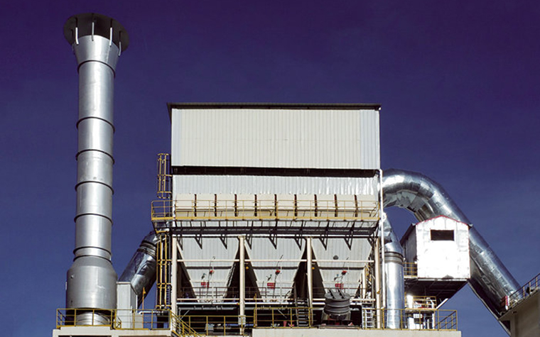
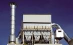
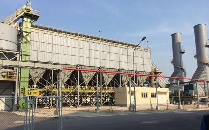
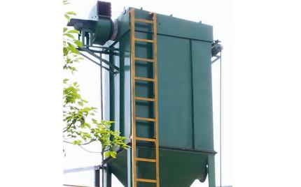
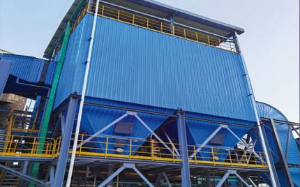
The LPMMC dust collection systems are developed based on the standard LPMC coal mill air-shock pulse-jet baghouses, specifically engineered for coal mill dust collection applications. It combines the advantages of compartmentalized reverse-air cleaning and pulse jet cleaning, and incorporates multiple fire and explosion prevention structures and measures, making it particularly suited for dust collection in coal pulverization systems.
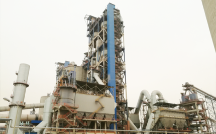
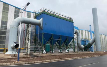
The LPMMC series is available in 33 specifications, with filtration areas ranging from 98 to 2,870 m² and airflow handling capacity from 4,100 to 155,000 m³/h. The product applies to blast furnace coal injection systems in steel plants and coal mill systems in cement plants, and has been successfully deployed at Hongta Dianxi Group, Guizhou Zunyi Saide, Henan Mengdian, and other enterprises, achieving excellent dust collection results.
High-pressure compressed air pulse jet cleaning delivers high cleaning intensity, suitable for high dust concentration applications.
Fire and explosion prevention: anti-static membrane-laminated polyester needle-felt filter media is employed; the main body adopts an explosion-proof structure; hopper cone angle exceeds 70° to prevent dust accumulation; self-locking pressure-relief explosion-proof doors are installed on the casing.
Automatic control: PLC-based control for cleaning and dust discharge; automatic temperature and pressure monitoring with alarm functions.
Fire suppression: nitrogen purging for cleaning, CO detection with alarm, and CO₂ fire suppression system.
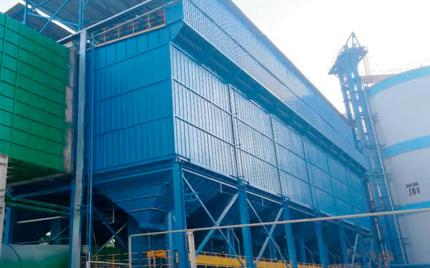
The dust collection systems employ a compartmentalized modular structure, operating as a bag filter that utilizes top-mounted pulse valves to sequentially perform compartment-isolated, damper-closed, plenum pulse jet cleaning (i.e., offline cleaning) on the filter bags in each chamber. The unit consists of the following major components:
Comprising the clean air chamber and the filter chamber. The clean air chamber houses the poppet valves, tube sheet, and pulse jet pipes. The filter chamber features explosion relief doors on the side panel and is internally fitted with filter bags and filter bag cages (support frames).
Available in multi-hopper or single-hopper configurations depending on equipment size. The hopper cone angle exceeds 70° to ensure smooth ash flow. Discharge valves are of the rotary airlock (star-wheel) type or flap valve type.
Includes the inlet and outlet ductwork and inclined baffle plates. For single-row configurations, the inlet/outlet wind box is positioned on one side of the housing. For double-row configurations, it is located in the center between the two rows. Smaller units of the Series A have no wind box; instead, the inlet and outlet ducts connect directly to the hoppers and the clean air chamber respectively.
Comprising pulse valves, compressed air reservoir (air manifold), pneumatic cylinders for poppet valve actuation, and their associated solenoid valves.
Filter-Regulator-Lubricator / FRL Assembly.
Including support columns, access ladders, and safety handrails.
Dust-laden gas enters through the inlet port of the inlet/outlet wind box and is redirected by the inclined baffle plates toward the hopper. As the gas velocity decreases, coarse particulate matter settles into the hopper by inertial separation. Fine dust particles are carried upward with the airflow into the filter chamber, where they are deposited on the outer surface of the filter bags by the filtration action of the accumulated dust cake. The cleaned gas passes through the filter bag walls into the upper clean air chamber, converges through the open poppet valves into the outlet wind box, and is finally discharged to atmosphere via the system induced draft fan.
When the control system issues a cleaning initiation signal, the cleaning cycle commences. The poppet valve of the first compartment is closed first, isolating it from the active airflow and taking that compartment offline. The corresponding pulse valve is then triggered, releasing a burst of high-pressure compressed air which, entraining additional air from the clean air chamber, is injected at high velocity into the filter bags. This causes the filter bags to rapidly expand and deform, dislodging the accumulated dust cake from the outer bag surface. The detached dust falls into the hopper below. After a prescribed settling period, the controller reopens the poppet valve, returning the compartment to online filtration service. This sequence is then executed successively across all remaining compartments until the complete cleaning cycle is finished.
The pulse jet cleaning process is governed by the controller and supports three control modes: differential pressure control, timer-based control, and manual control.
Under the differential pressure control mode, as filtration continues, dust progressively accumulates on the outer surface of the filter bags, causing a gradual rise in system resistance. When the pressure drop across the filter reaches the preset upper threshold, a cleaning initiation signal is triggered. The unit then cyclically executes the "pulse jet cleaning → settling → filtration" sequence compartment by compartment, until the system resistance falls back to the preset lower limit. This control mechanism maintains the operating resistance within a stable range at all times, ensuring the dust collector consistently achieves optimal collection efficiency at minimum energy consumption.