- Equity Code :832537
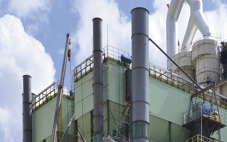
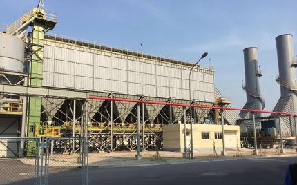
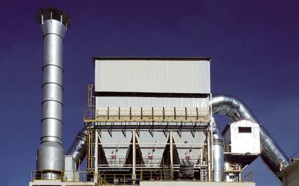
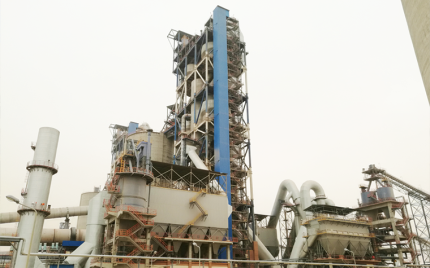
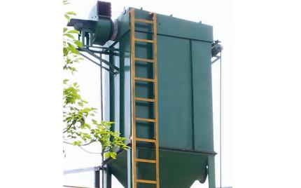
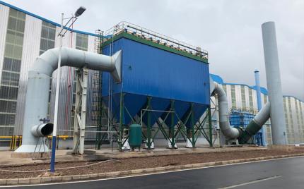
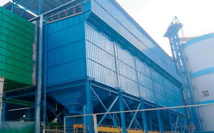
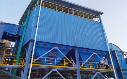
The LPMC baghouse filters are newly developed high-efficiency pulse-jet bag filters built upon the proven advantages of the LPM series. Compact in structure with a small footprint, it employs large-diameter pulse valves for compartment-wide simultaneous cleaning, delivering strong cleaning performance, reliable results, and long service life. Particularly suited for high-concentration dust applications, it is widely used in building materials, cement, metallurgy, machinery, chemical, and refractory industries for ultra-clean filtration of dust-laden exhaust gas, meeting ultra-low emission standards. The LPMC series comprises 4 families and 35 specifications, with filtration areas ranging from 120 to 4,462 m² and airflow handling capacity from 5,020 to 240,954 m³/h.
The LPMC baghouse filters adopt a compartmentalized assembly structure, comprising the main filter body, inlet/outlet air plenums, pulse jet cleaning system, hoppers and dust discharge mechanisms, and compressed air piping system.
Includes the clean air chamber, filter chamber, compartment partitions, and access doors. The clean air chamber houses the tube sheet, poppet valves, and blow pipes; the filter chamber accommodates the filter bags and bag cages.
Includes the inlet/outlet ducting and intermediate partition. Single-row models have the air plenums on one side; double-row models have them positioned between the two rows. The smaller Series A units have the air inlet located at the hopper and the air outlet at the clean air chamber.
Comprises pulse valves, air reservoirs, poppet valve cylinders, and solenoid valves.
Consists of hoppers, screw conveyors or air slides, and double-flap rotary discharge valves.
Dust-laden gas enters through the inlet of the air plenum, is redirected by the inclined partition toward the hopper, where the reduced flow velocity allows coarser particles to fall into the hopper under inertia. Finer particles are carried upward with the airflow into the filter chamber, where they are retained on the outer surface of the filter bags by the dust cake filtration layer. The cleaned gas passes through the interior of the filter bags into the clean air chamber, flows through the open poppet valves into the outlet plenum, and is discharged to atmosphere via the system fan.
When the control system issues a cleaning signal, the cleaning sequence initiates. The poppet valve of the first compartment closes, cutting off airflow through the filter chamber and taking that compartment offline. The pulse valve then opens, releasing high-pressure compressed air which, together with entrained clean air, is injected at high velocity into the filter bags, causing sudden bag expansion and deformation that dislodges the accumulated dust cake, which falls into the hopper. After a defined settling period, the poppet valve reopens, returning the compartment to active filtration (online). The process then proceeds sequentially through each remaining compartment until the complete cleaning cycle is finished.
Dust collected in the hoppers is discharged via screw conveyor or air slide to the ash storage silo.
The cleaning process is controlled by the control system, offering differential pressure, timed, and manual control modes.
Monitors the gradual rise in system resistance as dust accumulates on the outer surface of the filter bags. When resistance reaches the preset upper limit, a cleaning signal is triggered, and the system cycles sequentially through each compartment in a cleaning → settling → filtration sequence until resistance drops to the preset lower limit. This mechanism maintains system resistance within a stable range, ensuring optimal filtration efficiency and minimum energy consumption.
Initiates cleaning at fixed intervals based on empirical values, and is typically used for systems with stable operating conditions. During commissioning, the compartment offline duration and inter-compartment cleaning intervals can be adjusted through operational observation.