- Equity Code :832537
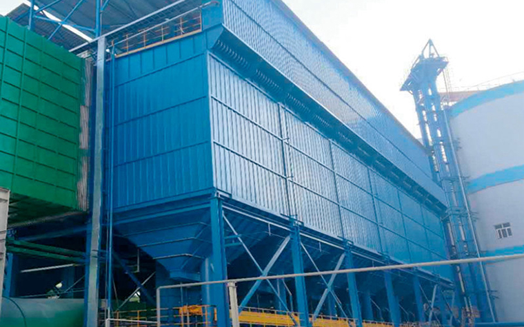
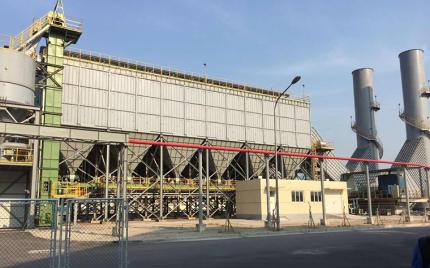
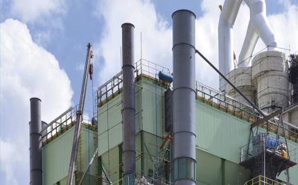
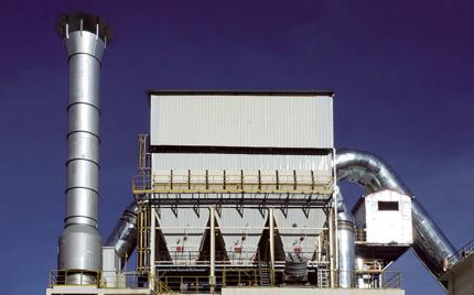
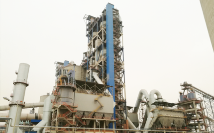
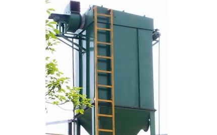
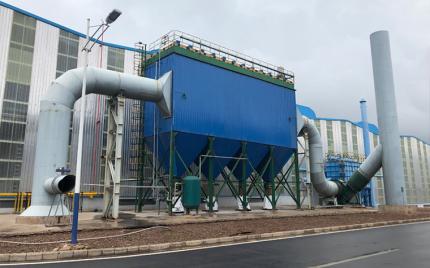
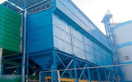
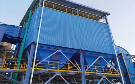
The JLNC industrial bag filters are high-efficiency long-bag pulse jet dust collection systems developed specifically for flue gas treatment in the electrolytic aluminum industry, capable of simultaneously handling particulate dust and hydrogen fluoride (HF) gas purification.
The unit incorporates a built-in dual-channel counter-flow two-stage dry adsorption purification system. Key features include: a Venturi gravity injection reactor on the secondary air duct; a multi-point circulation feeding control device, volute reactor, and alumina auto-regulation system on the primary air duct; an advanced airflow distribution system; online pulse jet cleaning; online monitoring; and top-lift large access doors. The electrical system employs PLC-based control with compartment pressure monitoring and integrated HF emission concentration measurement.
The JLNC delivers high-efficiency purification of HF gas and flue gas particulates, with strong flue gas handling capacity and convenient maintenance.
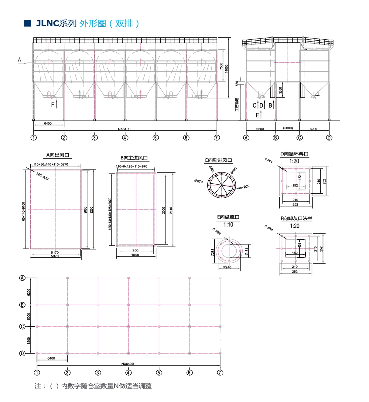
The filter is arranged in a double-row configuration. A Venturi reactor is installed in the air inlet duct of the secondary channel, while the main air duct is equipped with a multi-point feeding device and a volute reaction channel. The unit consists of components such as the hopper, flow equalizing device, lower housing, middle housing with the volute reaction channel, upper housing, filter elements, and rain shelter.
The filter starts up once the exhaust fan is activated. Driven by the exhaust fan, high-concentration alumina dust passes through the dual-channel reactor and enters the adsorption reaction channel, where fresh oxygen and fluorine-containing alumina are thoroughly mixed with the flue gas via two separate paths. An adsorption reaction then takes place, absorbing the hydrogen fluoride in the flue gas. After the reaction, solid materials such as the fluorine-laden alumina dust are carried together with the flue gas into the bag filter for separation. The flue gas first enters the dust collector's air inlet passage through the ductwork, passes through the flow-equalizing plate in the inlet passage, and enters the collector housing. As the cross-sectional area expands, the gas velocity decreases, allowing the flue gas to flow more evenly through the descending flue within the housing. Due to the downward turn of the airflow and the further reduction in gas velocity, coarse dust particles settle directly into the hopper by inertial separation, while fine dust particles are carried by the airflow into the filtering chamber and reach the surface of the filter bags, where the dust accumulates. The filtered gas then enters the upper housing and the exhaust duct, and is discharged into the atmosphere via the fan. As the dust layer accumulated on the outer surface of the filter bags reaches a certain thickness, causing the pressure differential between the collector's inlet and outlet to reach the set value, pulse-jet cleaning of the filter bags begins. Purified compressed air is discharged through pulse valves mounted on the air distribution box at the top of the collector, jetting into the filter bags to remove the dust from their outer surfaces. The entire cleaning process is controlled by a differential pressure gauge together with a PLC (Programmable Logic Controller).