- Equity Code :832537
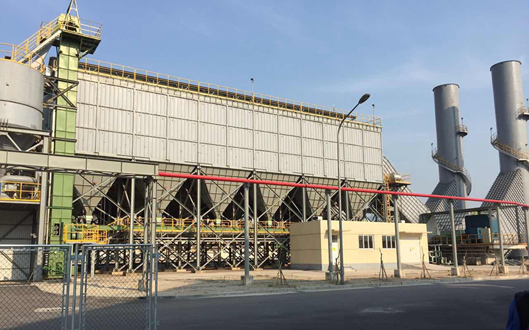
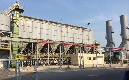
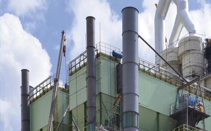
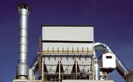
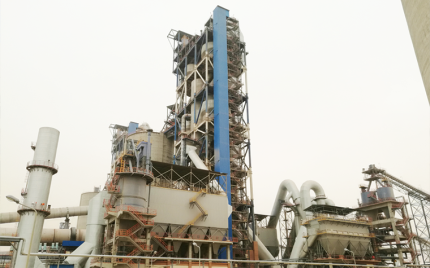
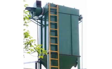
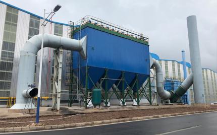
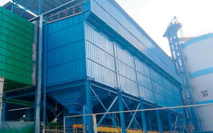
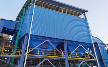
The LCMC series pulse jet bag filters are a new generation of low-pressure pulse-jet baghouse developed on the basis of the design and manufacturing experience of the LCM type, combined with the ultra-low emission requirements of the steel and machinery industries. The product retains the advantages of the original long-bag pulse-jet dust collectors and fully leverages the benefits of pulse-jet cleaning. It uses temperature- and corrosion-resistant, high-filtration-precision filter media and is applied to ultra-clean filtration of flue gas from iron tapping floors, ore bins, converters, electric furnaces, and sintering machines in the steel industry, meeting ultra-low emission requirements. It has been developed into a series of high-efficiency bag filters capable of meeting various air volume requirements in the steel industry, and can also be used in other types of large-scale dust removal projects.
This kind of pulse jet bag filter employs a compartmentalized design with a central intermediate duct inlet configuration. Dust-laden flue gas enters each compartment's hopper through the central inlet and wedge-shaped air distribution duct. Within the hopper and before entering the filter chamber, coarser particulates are separated and fall directly into the hopper through the combined action of baffle deflection and inertial gravitational settling. The remaining finer particulates are carried upward with the gas stream into the filter bags within each compartment. Upon filtration, the particulates are retained on the outer surface of the filter bags, while the cleaned gas passes through the interior of the filter bags into the clean air plenum. The cleaned gas subsequently passes through the offline isolation valve (disc lift valve) into the outlet air duct and is finally discharged into the atmosphere via the outlet, induced draft fan, and exhaust stack.
Dust accumulated in the hoppers is conveyed to the ash storage silo via rotary discharge valves, a drag chain conveyor (cut-in scraper conveyor), a collecting scraper conveyor, and a bucket elevator. The stored ash is subsequently discharged and transported by means of a humidifier or pneumatic extraction system.
As filtration time progresses, particulate accumulation on the outer surface of the filter bags increases continuously, causing a gradual rise in the differential pressure across the dust collector. Once the differential pressure reaches the pre-configured threshold, the PLC control system initiates the cleaning sequence as follows:
The pulse jet bag filters employs a PLC-based control system to manage the bag cleaning operation. Depending on project-specific requirements, the system supports both manual and automatic control modes. The automatic control mode is further divided into three configurations: time-based control, differential pressure-based control, and a hybrid time-differential pressure control mode. The time-based control mode generally involves setting parameters such as pulse interval and cycle interval. The differential pressure control mode uses the total system differential pressure as the trigger condition for each cleaning cycle initiation. Typical operating parameters are as follows: pulse width ">0.1–0.15 s, pulse interval ">10–20 s, and cycle interval ">30–90 min. The compressed air pressure required for cleaning control shall be determined in accordance with the solenoid pulse valve specifications and the upper jet injection parameters, with a general operating range of ">0.25–0.35 MPa.
1. The Selection of Filtration Velocity
Filtration velocity refers to the air velocity passing through the filter bag media (m/min). It is sometimes called the air-to-cloth ratio, referring to the volume of air passing through a unit area of filter media per unit time (m³/min/m²), which simplifies to m/min. The filtration velocity should be determined based on the characteristics of the dust and flue gas, temperature and humidity, dust concentration, cleaning method, and the properties of the selected filter media. Filtration velocity not only determines the size of the dust collector, but also significantly affects the resistance across the filter media, dust collection efficiency, cleaning efficiency, and filter bag service life. To ensure stable and reliable operation of the dust collector, the filtration velocity must be determined through comprehensive consideration of these factors.
2. The Selection of Filter Media
Filter media and filter bags are the core components of a bag-type dust collector. The quality of the filter bag material directly determines key performance indicators such as the size and specification of the dust collector, operating resistance, emission concentration, and service life. Selection principles: by material type, options include standard polyester, anti-static, corresponding ultra-fine needle-punched felt filter media, or membrane-coated filter media. The fabric weight can also be adjusted as required, with 550 g/m² being the most commonly used specification.
3. Pulse Valves
3-inch submerged pulse valves are used, with a blowing pressure of 0.25–0.35 MPa. The specific pressure depends on the number of filter bags being cleaned and the pulse valve configuration.
4. Filter Bag Cage (Support) Longitudinal Ribs
The number of longitudinal support ribs on the filter bag cage is selected according to the filter media: standard media typically uses 12 ribs, while composite filter media uses 16 ribs with a silicone-treated surface.
5. Cleaning Control Method
An offline cleaning method with sequential time-based control is used, with the cleaning cycle adjusted according to changes in resistance. The operating resistance of the dust collector is generally controlled within the range of 1000–1500 Pa. A combined time/differential-pressure control method may also be used.
6. Ash Discharge and Layout Options
Ground-level layout: Rotary airlock valve → ash conveying scraper conveyor → collecting scraper conveyor → bucket elevator → ash storage silo → dust humidifier or vacuum suction device.
Elevated layout: Rotary airlock valve → ash conveying scraper conveyor → collecting scraper conveyor → ash storage silo → dust humidifier or vacuum suction device, or discharged directly into a tanker truck.
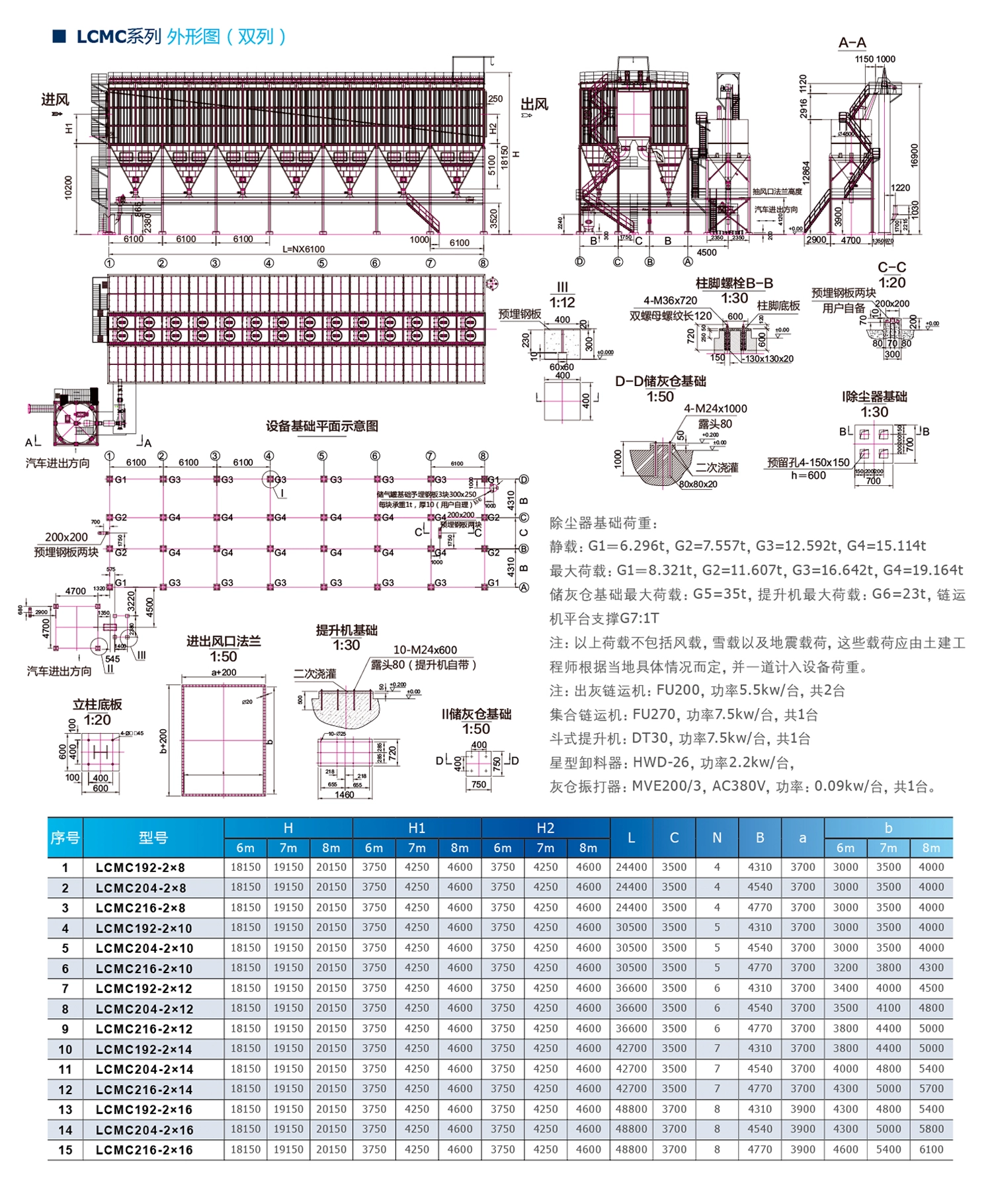
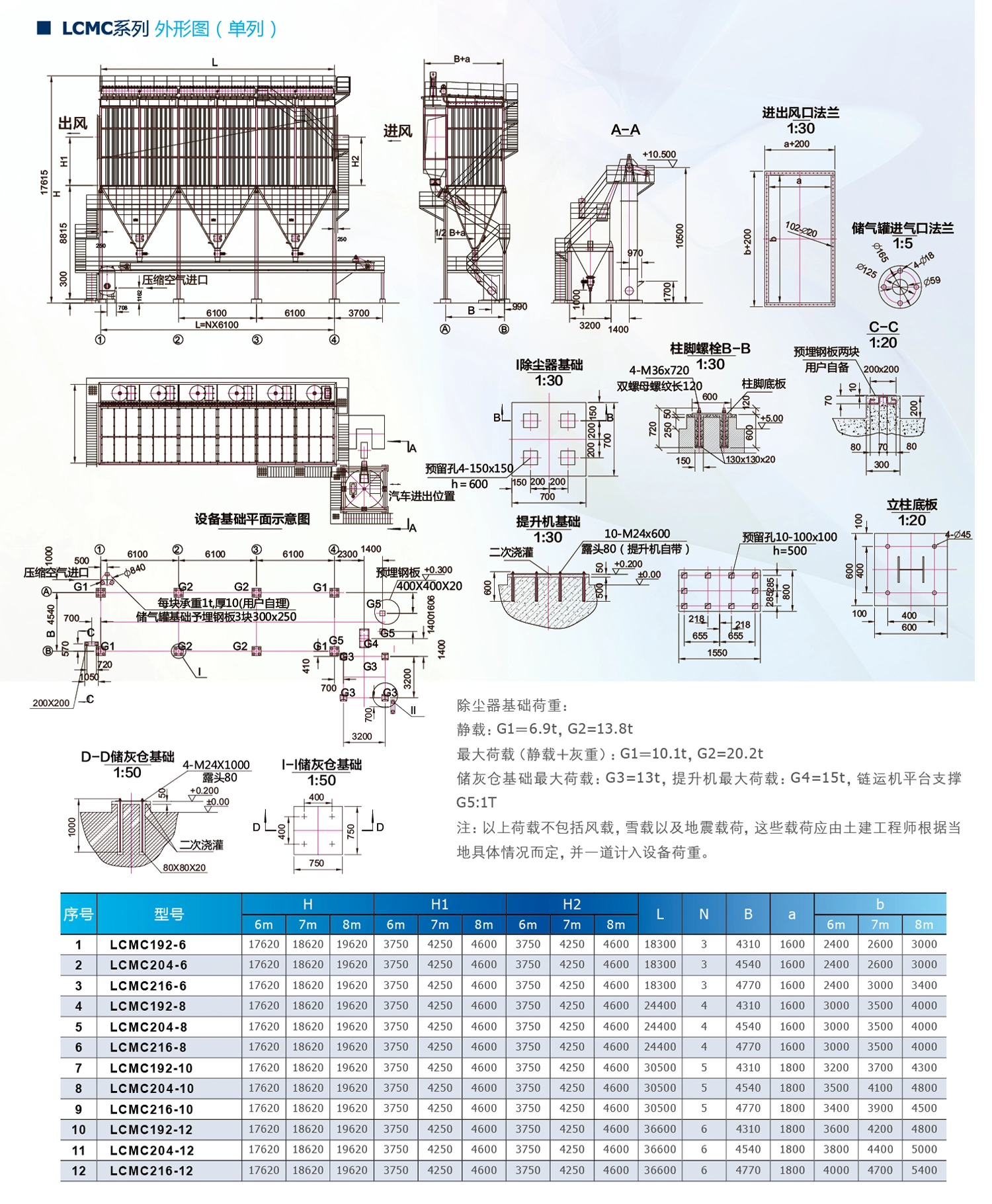
1. The LCMC-type low-pressure long-bag pulse-jet dust collector uses a single-nozzle jetting method, with each of the 12 pulse valves cleaning 16–18 filter bags. Together with the number of units, this results in a total of 12 product specifications.
2. The inlet dust concentration of the dust collector is generally less than 30 g/Nm³; if special requirements exist, the design can be customized according to the customer's needs.
3. The technical performance of the LCMC-type long-bag pulse-jet dust collector is shown in the table "Performance Parameters of LCMC-Type Long-Bag Dust Collector."