- Equity Code :832537
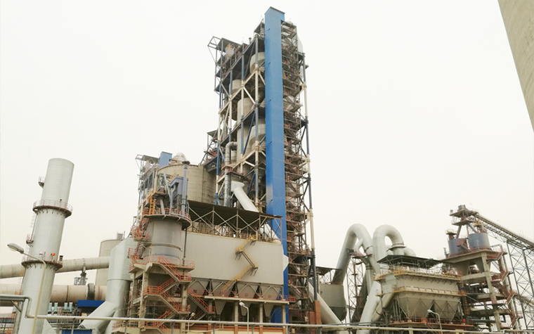
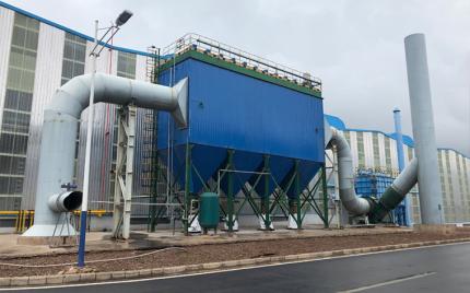
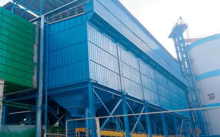
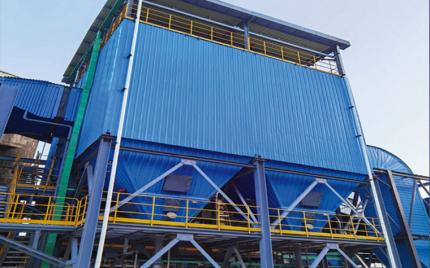
The LCMG-C pulse jet dust collectors are developed based on the LCMG-Ⅱ series, specifically engineered for kiln head and kiln tail applications in cement production. It retains the advantages of high-temperature long-bag pulse jet filtration while fully utilizing the benefits of pulse jet cleaning. The product employs high-temperature and corrosion-resistant filter media, high-temperature structural design, and anti-thermal deformation measures, for ultra-clean filtration of high-temperature flue gas at cement kiln head and tail positions, meeting ultra-low emission standards. The product line covers a full range of high-efficiency dust collectors suited for cement production lines with daily outputs of 5,000 t/d to 10,000 t/d.
The LCMG-C pulse jet dust collectors adopt a compartmentalized design with a central intermediate duct inlet. Dust-laden flue gas enters each compartment's hopper through the central inlet and wedge-shaped air distribution duct. Within the hopper and before entering the filter chamber, coarser particles are separated by baffle deflection and inertial gravitational settling and fall directly into the hopper. Finer particles are carried upward into the filter bags, where they are retained on the outer surface. The cleaned gas passes through the interior of the filter bags into the clean air plenum, then through the offline isolation valve (multi-leaf butterfly valve or disc lift valve) into the outlet duct, and is discharged to the atmosphere via the outlet, fan, and exhaust stack. Dust accumulated in the hoppers is conveyed to the kiln dust storage facility via rotary discharge valves and FU chain conveyors.
As filtration progresses, dust accumulation on the outer surface of the filter bags causes a gradual rise in system resistance. When resistance reaches the preset threshold, the PLC issues a cleaning signal, first closing the poppet valve of the designated module to isolate that compartment, then triggering the solenoid pulse valve to release compressed air in a 0.1–0.2 s burst through the blow pipes and nozzles into the filter bags. The induced effect of the high-velocity jet entrains a large volume of clean air from the clean air plenum into the bags, causing sequential top-to-bottom expansion until the bags reach their elastic limit, whereupon the restoring tension generates a reverse acceleration, producing high-frequency oscillatory deformation that dislodges the accumulated dust cake. After a defined settling period, the poppet valve reopens and the compartment returns to filtration duty, while the next module enters its cleaning cycle. This sequential cleaning → standby → filtration cycle repeats continuously, maintaining system resistance within a defined range for sustained long-term operation.
The PLC-based cleaning control system supports manual and automatic modes. Automatic control is divided into time-based, differential pressure, and hybrid time-differential pressure modes. Time-based mode configures parameters such as pulse interval and cycle interval; differential pressure mode uses total system ΔP as the trigger condition. Typical parameters: pulse width 0.1–0.15 s, pulse interval 10–20 s, cycle interval 30–90 min. Compressed air pressure is determined by pulse valve specifications and jet parameters, generally 0.25–0.35 MPa.
1. Selection of Filtration Velocity
Filtration velocity is the velocity (m/min) of airflow passing through the filter bag media. It is sometimes referred to as the air-to-cloth ratio, meaning the volume of air passing through a unit area of filter media per unit time, in units of m³/min/m², which simplifies to m/min. The selection of filtration velocity must be determined according to the characteristics of the dust and flue gas, temperature and humidity, dust concentration, cleaning method, and the properties of the filter media selected. Filtration velocity not only determines the size of the dust collector, but also has a significant impact on the resistance across the filter media, dust collection efficiency, cleaning efficiency, and the service life of the filter bags. To ensure the dust collector operates stably and normally, the filtration velocity must be determined based on comprehensive consideration of all these factors.
2. Selection of Filter Media
The filter media and filter bags are the core components of a bag-type dust collector. The quality of the filter bag material directly determines the dust collector's specifications and size, operating resistance, emission concentration, service life, and other performance indicators. To date, the filter media mainly used in dust removal projects at cement kiln heads and kiln tails include glass fiber membrane-coated filter media, P84 filter felt, NOMEX filter felt, Fluormesh (a composite filter material), among others.
Selection principles: For P84, imported NOMEX filter media, and glass fiber membrane-coated filter media, a higher filtration velocity may be selected, typically 0.95–1.1 m/min; for conventional domestic filter media and composite filter media, a lower filtration velocity is preferred, typically 0.8–0.95 m/min. A lower velocity should be selected for high-concentration conditions, while a slightly higher velocity may be selected for low-concentration conditions.
3. Pulse Valves
3" submerged-type pulse valves are used, with a jetting pressure of 0.25–0.35 MPa. The selection is related to the number of filter bags being cleaned and the pulse valve specifications.
4. Filter Bag Cages
Filter bag cages are produced on an automated welding production line, with a Venturi protective tube at the top opening. The number of longitudinal wires is selected according to the filter media used: typically 12 wires for conventional media, 16 wires for Fluormesh filter media, and 20 or more wires (commonly 24) for glass fiber membrane-coated filter media.
5. Cleaning Control Method
The dust collector generally adopts an off-line cleaning method, with the control program operating on a time-sequenced basis; the cleaning cycle is adjusted according to changes in resistance. The operating resistance of the dust collector is generally controlled within the range of 1000–1500 Pa.
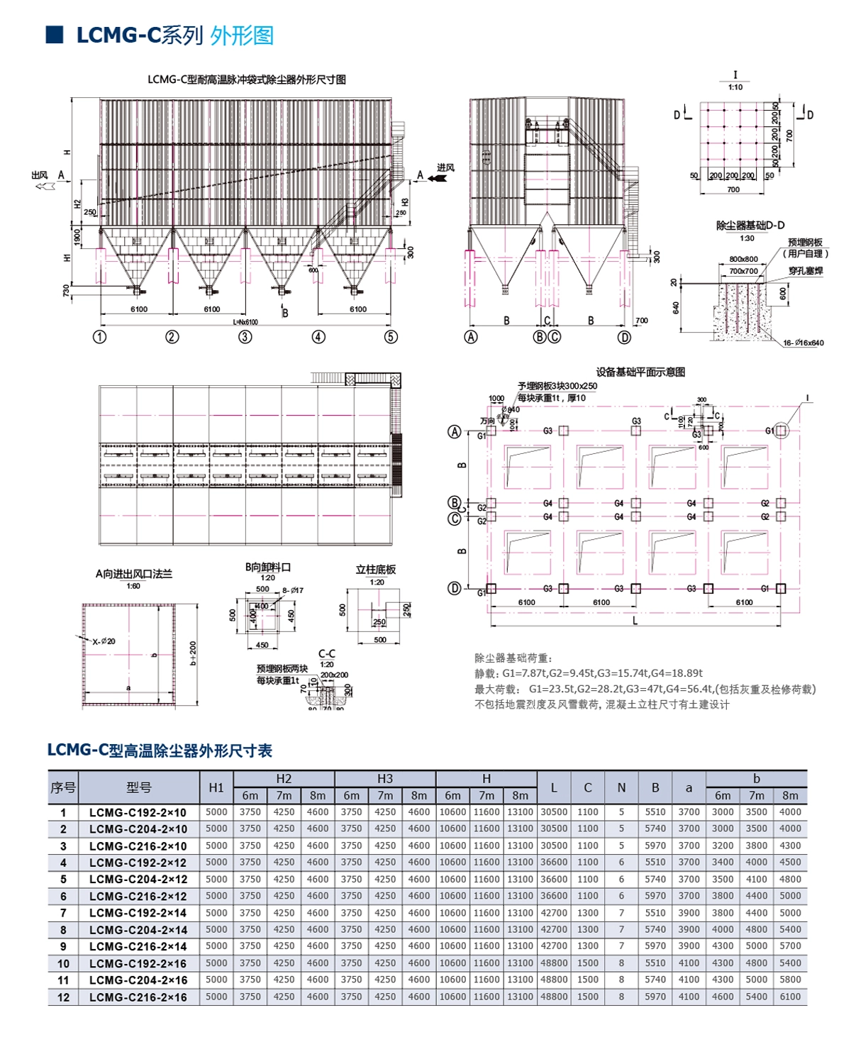
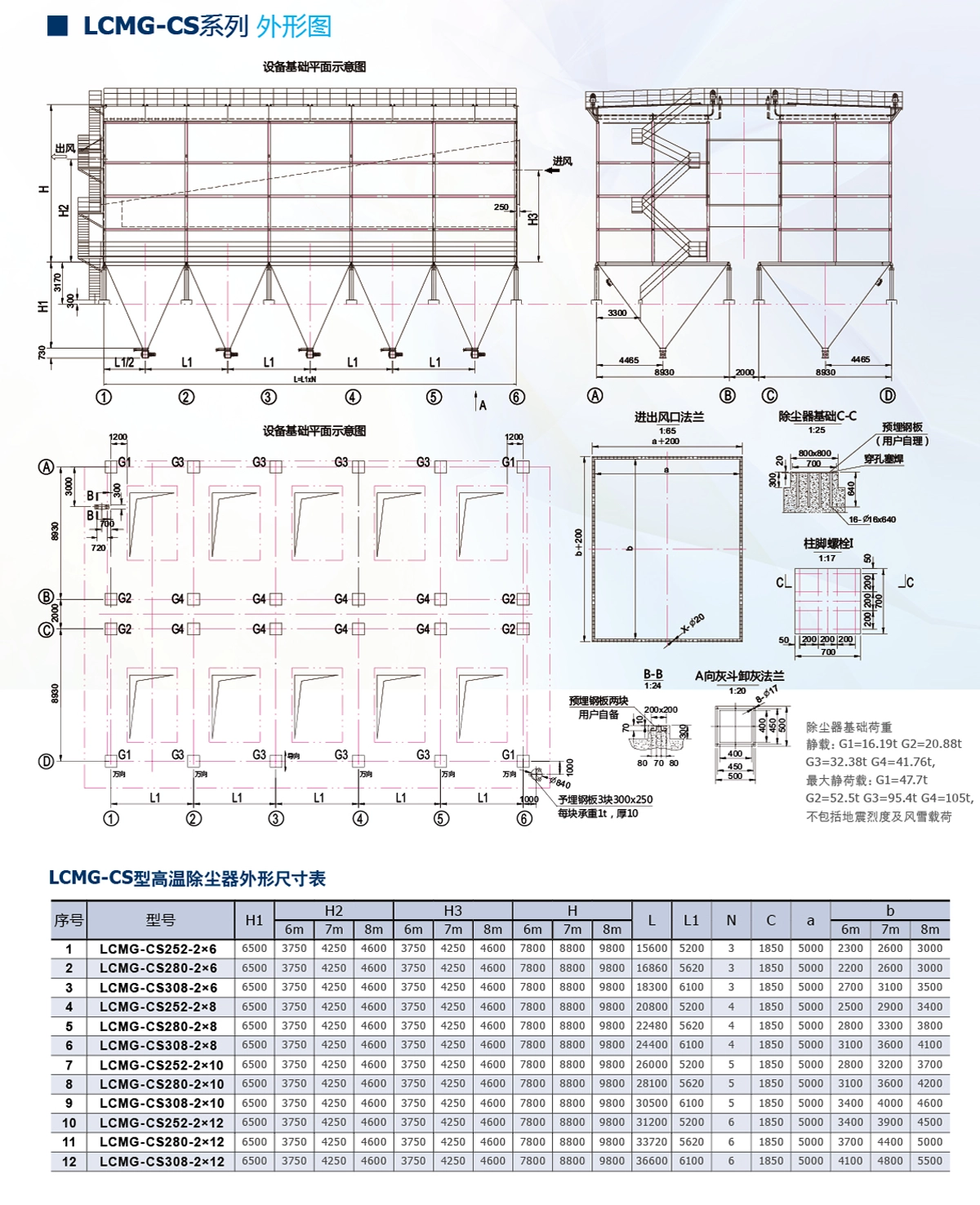
1. The LCMG-C type high-temperature long-bag pulse-jet dust collector uses a single-nozzle jetting method, with each of the 12 pulse valves cleaning 16–18 filter bags. Together with the number of units, this results in a total of 12 product specifications. The LCMG-CS type features a dual-nozzle, single-channel structure, with 9, 10, or 11 pulse valves cleaning 14 filter bags each. Together with the number of units, this also results in a total of 12 product specifications.
2. The inlet dust concentration of the dust collector is generally permitted up to 100 g/Nm³; if special requirements exist, the design can be customized according to the customer's needs.